MyGoodLadyWife has been wanting to assemble another electronic kit. Meanwhile, I have been looking for something to assist me in learning morse code. I have a plan!
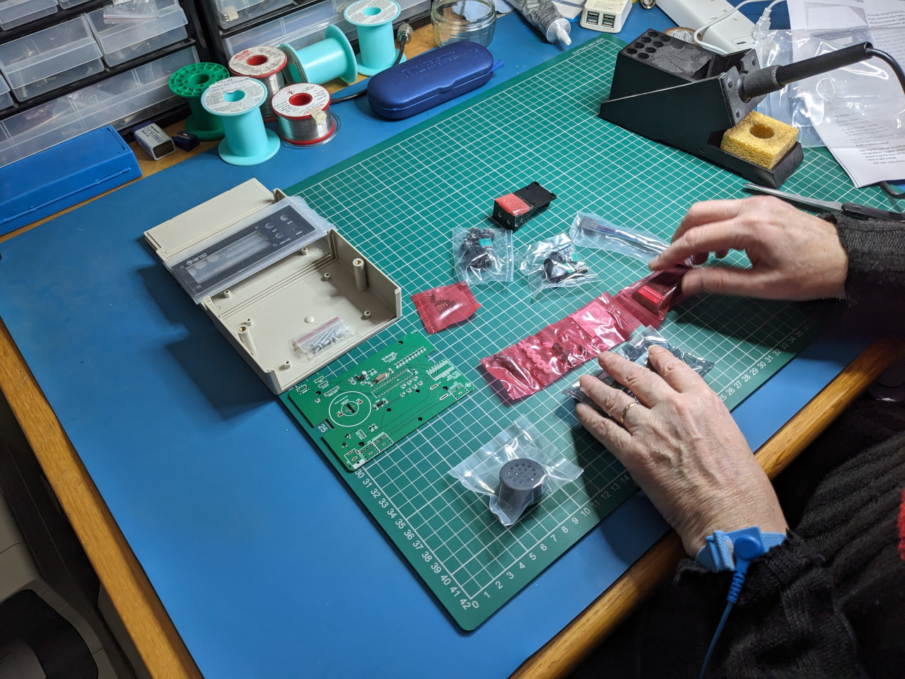
Here it is, ready on the workbench waiting for MGLW to do her stuff…
FMT4 unopened kit on workbench
MGLW got to work unpacking the kit, reading the instructions and checking that the parts were all there and in good condition.
MGLW sorting the parts
Construction proceeded quickly and easily…
MGLW is making good progress
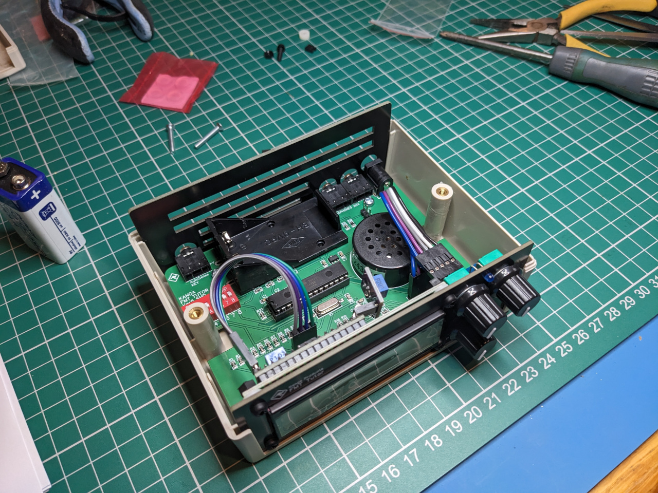
It did not take too long before the build was complete and ready for powering up!
The construction is complete. Just the lid to add…
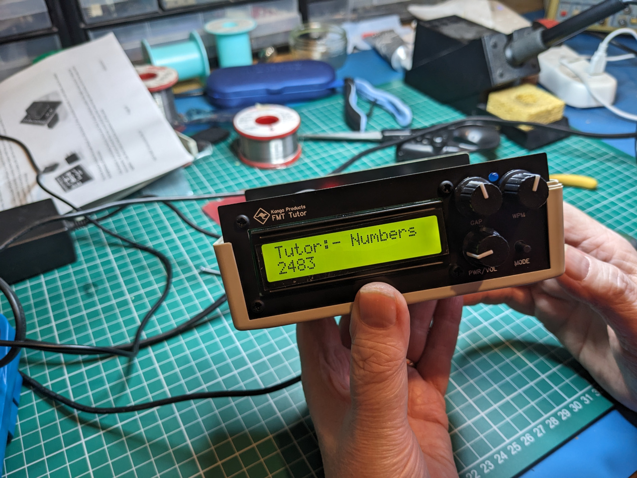
Finally… power was applied and… the room was filled with the sound of morse code!
The unit powers up and sends out morse code
MGLW enjoyed building this kit very much. She was pleased with the quality of the kit – the PCB and components were well packed and arrived undamaged. There were one or two area of the instructions that she felt were slightly ambiguous, but she was able to work everything out in the end.
I have enjoyed using this device for my sending practice – my iambic keyer works well with this device and the various different tutor modes are very helpful when learning CW. I especially like the contest mode where it slightly changes the pitch of each ‘contact’. Fun!
I’m sure there will be more kits for MGLW to build soon. I have my eye on some goodies from QRP Labs next…
David 2E0DYN and myself spent two days in the lab working on the signal generator, removing old capacitors, cleaning here and there and finally fitting new components.
One problem we encountered was the poor state of the original mains filter capacitors. The plastic bodies had either cracked and broken, or the ends of the bodies were coming away from the wire. These would all be replaced.
The mains filter caps were in a poor state
The original devices were replaced with suitable safety rated devices
In many cases we had to replace old ‘can’ style electrolytic capacitors that would have dried out over time. These would be replaced with modern ‘motor’ capacitors that have similar high voltage and capacitance characteristics.
‘Old’ and ‘new’ style electrolytics side by side
The old ‘can’ in the above picture would pose a challenge, as it contained multiple capacitors in one device. We would have to find some way of replacing it with a bank of individual capacitors.
‘Hybrid’ capacitor replacing original multi-device ‘can’
There were also some alterations made underneath the power supply. The original capacitors had large lugs on them that allowed other wires and components to be directly soldered to them. The new ‘motor’ capacitors had a pair of flying leads instead. It was necessary to fit some tag strips to allow everything to be reconnected.
Tag strip allowing connections to be made
Finally the power supply section was ready, having had the necessary component changes and tag strips fitted.
Underside of completed PSU section
There were of course many other components to replace, including several that required some major disassembly of the front panel to allow access.
There were some hard to get to places needing lots of work with screwdrivers and small spanners
Things were progressing well by now. The replacement components were all fitted and work began on the physical reassembly of the unit.
The unit is reassembled prior to testing
Finally after a few hours of the second session in the lab, we could do a test power-up of the device. This would be the first time in several decades that this unit had come alive.
The device is working for the first time in many years
Here is the output on the oscilloscope. (Yes, the Gould scope is back in the equipment stack. The HP is fun to use but it is very noisy). A nice clean waveform was observed. The set was then hooked up to my DX394 receiver where we were able to test the output of both continuous wave and amplitude modulated signals from the unit.
I knew that when the signal generator arrived on the bench, it would not be safe to just plug it in and ‘suck it and see’. There was a very good chance that some components had failed with old age and this could result in some fireworks and a severely damaged unit if power was applied.
Unfortunately I have little experience in restoring old valve-based equipment. However, I was able to call on the expert advice of David 2E0DYN who is quite the boffin on valve equipment in general and even better, he has recently renovated his own TF995A. My unit was in safe hands!
We set to work, removing the six bolts in the front face which allowed us to slide out the main chassis from the case. The power supply is built in to the bottom of the case and is connected to the chassis by a six-pin plug.
The chassis connects to the PSU with this six pin connector plug
One interesting aspect of this renovation is that unlike a lot of modern equipment, the TF995A is clearly designed to be disassembled for servicing and repair. We had access to the original Marconi instruction/service manual which allowed us to compile a list of components that would need replacement.
Typical old electrolytic capacitor cans scheduled for replacement with modern parts
A decision was made at the outset – old capacitor cans such as these would be replaced with modern parts. This would not be a ‘historical’ restoration trying to return it to some sort of factory finish, but a repair with the intention of putting this unit back in to service to do useful work and add more to its life story.
Two banks of capacitors that all need to be replaced
David’s eagle eyes spotted some failed capacitors deep within the mains filter requiring the disassembly of the filter.
The mains input filter before disassembly
There was also work to be done underneath the power supply section. This was removed from the case and inspected for components needing replacement, as well as planning the routing of replacement cabling.
The underside of the power supply showing some of the wiring
Finally, it would be necessary to strip down part of the front panel. This would permit the removal of a sub-assembly attached to the back face of the panel. Sandwiched in between this sub-assembly and panel were more components needing attention.
The front panel was stripped down to allow access to screws holding the sub-assembly in place
After a few hours of work, we had a list of components to buy and jobs to be done. The next post will show the work being done.
I have an uncle who for for many years up until his retirement worked as an engineer for the UK Civil Aviation Authority. At some point during his career he was able to purchase an old Marconi signal generator that has become surplus to requirements.
Years passed and the signal generator quietly gathered dust up in the attic until a recent clearout saw it delivered to the workbench of G7IVF to see if possibly, just possibly, it might find a home here. Silly question really…
However, because the unit hasn’t been powered up for a considerable amount of time, it is safest to assume that some investigation and repair work will be necessary. More to come on this…
Meanwhile here are some pictures of the generator as well as an interesting piece of history in the form of a label that was attached to the unit showing it was withdrawn from service and placed in to storage in 1976 before being sold on.
The Marconi TF995A/5 sits hopefully on the bench of G7IVF
Bright sunlight after so many years in the attic. The Marconi is suddenly full of hope…
Yes! It’s going to become part of the radio station G7IVF. A happy signal generator!
Part of the ongoing history of this unit – the original label from the CAA.
The last time this unit was used properly – 1976. Forty years on, the story is about to continue…
I have a few days off from work and it seemed like an ideal opportunity to tidy up my electronics bench. This would allow me to change out my old Gould 20MHz oscilloscope for something different.
In this case, the something different is a Hewlett Packard 54200A Digitizing Oscilloscope. I know it powers up, but as yet I don’t know if will serve as a reliable instrument for my experiments. Time will tell…
The NRD-525 that was recently on the bench has gone back to the M6BOH/M6JOJ shack, but not before I had a chance to use it on my recently constructed random long-wire and 9:1 un-un. I had some fun getting the hang of decoding HF weather faxes using the FLDigi package which can be obtained from W1HKJ Software – home of FLDigi
Typical HF weather fax image received using JRC NRD-525
The image looks slanted because I have not spent time calibrating the sound card on my laptop. I’ll come back to that another time…
My friend Brian M6BOH inherited a JRC NRD-525 receiver which at first glance seemed in good condition.
JRD-525 on the bench for some TLC
However, it soon became clear that all was not well. The set could be tuned with the large tuning knob, but several keys on the number pad would not work. Closer inspection revealed that the set had met up with a cup of coffee and the encounter had not ended well for the radio.
Coffee damaged keypad
Once the radio was disassembled we could see the damage to the circuit board. With a bit of gentle persuasion some of the keys were returned to life with a stiff brush and some isopropyl alcohol, but others were beyond hope and needed replacing.
Coffee has got in to several of the switches. Not all could be saved and so would need replacing.
MyGoodLadyWife agreed to do the surgery for us on this occasion and after cleaning the coffee stained area thoroughly she then removed the dead switches.
MGLW gathering up the removed dead switches.
MGLW then cleaned up the circuit board ready to receive new switches. The original JRC service manual lists a part number that allowed us to buy the exact replacement part from Farnell which was lucky indeed. They were cheap too, so we bought a good stock of them in case more are needed in the future.
MGLW has removed the dead switches.
Finally, the part MGLW likes best – soldering in new parts. Within a few minutes the new switches were fitted and we were re-assembling the radio ready for testing.
MGLW has finished the repair. Now to re-assemble and test.
So… power on, tune up and… it works! I’ll do some experiments over the next few days and post up some of the results…
Several times a month I take part in the UKAC VHF contests on 6 and 2 meters. One of the problems I faced was that after a few minutes of calling CQ if the band was quiet, my voice was starting to get tired and croaky. I had thought about using a voice keyer, but it means extra kit to carry and provide power for when operating portable.
I recently heard about a modification you can make to the stock Yaesu microphone, by replacing the circuit board with a new one containing both a voice keyer as well as a speech compressor. This had to be checked out at once!
Now, be warned. This is a kit of parts to assemble, not the finished product. However, the surface mount part is already soldered to the PCB. All you have to do is add the conventional components and some link wires.
Fortunately for me, MyGoodLadyWife loves to do soldering, so she was more than happy to assemble the kit when it arrived. (Lucky me!)
Here’s how the finished item looks, ready for final fitting in to a new microphone housing I bought along with the kit.