David M0ICZ invited me to this year’s Lambourn Vintage Machinery Society 2017 show. Part agricultural show, part auto jumble and part vintage vehicle and machinery exhibition, it was a fascinating day out. I was particularly keen to go, as David had been working very hard in restoring his 1941 Austin K2 van so that he could display it.
1941 Austin K2, proud to be on display at Lambourn in May 2017Austin K2 information boardAnother view of the K2K2 Rear view
Another item that will always get my attention at these sort of events is the static engine. Little Lister and Petter engines that pop and burble away happily, pumping water or generating electricity are fascinating. Lambourn had a very good selection this year – here are just some…
Small static engine just idlingEngine driving a very nice red pumpA combination Lister engine and pump set
There are always some rarities and oddities at these shows. The rare…
Its time to power up the Pi and its touch screen. It is necessary to apply two sources of power, one for the screen and one for the Pi. I bought a suitable cable from SmartiCase at the same time as the case itself.
USB Splitter cable for powering two devices.
Place the two micro-USB plugs carefully in to the sockets – its a bit fiddly – and trail the cable away from the back of the device.
Fitting the micro-USB power leads.
Now to power up!
Oops! The wrong OS.
Oh dear. I forgot to wipe the SD card from the last time I used the Pi, helping to test a friend’s arcade machine build. Now here’s where things get fiddly. It will be necessary to undo the screws on the audio hat in order to allow its extraction before the trap-door can be opened and the Pi flipped out to allow the SD card to be extracted and replaced. Give me a moment to burn a new image on the card…
While I’m preparing a new Raspian image, let’s have a look at Hector having fun checking the case for Lego compatibility…
Hector checking Lego compatibilityHector with the old Pi2 in its SmartiCase, down from the attic after working as a Dump1090 server.
OK, the SD card is now loaded with Raspbian. Lets see how it looks…
Raspian on the touch screen. It worked first time out of the box.
It works beautifully. I plugged in a USB souncard into the hub that is powering everything and used it to hook up to one of my radio receivers. (Note, the Pi-DAC is for high quality audio output only. There is no line in). Forty metres was quite lively so I installed FLDIGI and tuned to the PSK section of the band…
Decoding PSK31 on forty metres.
It works beautifully. There is no jerkiness or lag on the waterfall display. I had to tweak the microphone level a bit to prevent it overloading. Finally I tried a screen capture on the Pi.
DD2MON in a conversation or ‘QSO’ with F4HGE on forty metres PSK31.
I mentioned in the last post that I had another treat in store for my lucky little Pi. This comes in the form of an audio ‘hat’ that the SmartiPi Touch is designed to accomodate. Let’s see what it looks like and how to fit it…
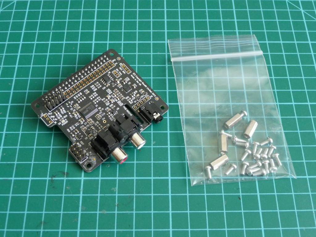
A brand new Pi-DAC board for output to an audio amplifier or headphones.
The bare hat and mounting kit.
We will not need the supplied mounting kit, but instead we will use the two small black spacers and screws supplied with the screen case. Place the spacers on the case over the screw holes and push the long black connector in the the corresponding slot and on to the pins on the Pi circuit board.
The hat is in place, plugged in to the Pi and screwed to the back of the case.
In the next post I will go in to applying power to the Pi and screen and show some of the results.
Here is how a fitted I Raspberry Pi 3 with a 7-inch touch screen using a SmartiPi Touch case.
Start off by placing four sticky feet on the base.
Adding the sticky feet to the base
Now we move on to the ‘door’ at the back of the case. Find one of the small rubber patches…
Trap door and rubber patch.
…and stick it in place.
All done.
There is another of these patches to fit to the back of the case…
Fit patch to the top right of the case rear.
Case is now prepped.
Next up is to offer the base up to the case hinges and fit the two bolts. It is important not to tighten these bolts too much or the hinge will not operate.
Checking hinge alignment.
Fit the supplied ribbon cable to the slot in the back of the display screen control board with the silver contacts facing up…
Check the silver contacts. They must face up where they slot in to the control board.
…and offer up the screen to the case, threading the ribbon cable through.
Thread the ribbon cable through carefully.
Once in place, the screen can be fixed in to the case with four black screws.
Screw the screen in to place with four black screws.
Now let’s fit the Pi. Again, look carefully at how the ribbon cable exits the case and orientates with the Pi’s connector.
Careful how you orient the ribbon cable.
Slide the pi in to place and it will mate up with two small pegs in the recess where the Pi sits. At this point you may fix the Pi in place with two screws leaving the board accessible for experiments. However, at this point I will fit the trap door I prepared earlier.
The trap door holds the Pi in place without screws allowing quick access.
In the next post, another treat for a very deserving little Pi…
I have treated one of my Raspberry Pis to a new 7-inch touchscreen which I intend to house in a SmartiPi Touch from SmartiCase. This is another project I have sponsored through Kickstarter.
A freshly prepared SmartiPi Touch.
The corresponding 7-inch touchscreen ready for mounting.
Unpacking and checking the parts.
As you can see I have ordered the camera case for later experimentation. The allen key is supplied to fit the hinge bolts as well as an option to discard the base and mount directly to a larger surface or even a VESA monitor arm.
In the next post I will describe how to assemble the screen in to the original base. In the meantime, why not go to the SmartiCase website and have a look…
David 2E0DYN and myself spent two days in the lab working on the signal generator, removing old capacitors, cleaning here and there and finally fitting new components.
One problem we encountered was the poor state of the original mains filter capacitors. The plastic bodies had either cracked and broken, or the ends of the bodies were coming away from the wire. These would all be replaced.
The mains filter caps were in a poor stateThe original devices were replaced with suitable safety rated devices
In many cases we had to replace old ‘can’ style electrolytic capacitors that would have dried out over time. These would be replaced with modern ‘motor’ capacitors that have similar high voltage and capacitance characteristics.
‘Old’ and ‘new’ style electrolytics side by side
The old ‘can’ in the above picture would pose a challenge, as it contained multiple capacitors in one device. We would have to find some way of replacing it with a bank of individual capacitors.
‘Hybrid’ capacitor replacing original multi-device ‘can’
There were also some alterations made underneath the power supply. The original capacitors had large lugs on them that allowed other wires and components to be directly soldered to them. The new ‘motor’ capacitors had a pair of flying leads instead. It was necessary to fit some tag strips to allow everything to be reconnected.
Tag strip allowing connections to be made
Finally the power supply section was ready, having had the necessary component changes and tag strips fitted.
Underside of completed PSU section
There were of course many other components to replace, including several that required some major disassembly of the front panel to allow access.
There were some hard to get to places needing lots of work with screwdrivers and small spanners
Things were progressing well by now. The replacement components were all fitted and work began on the physical reassembly of the unit.
The unit is reassembled prior to testing
Finally after a few hours of the second session in the lab, we could do a test power-up of the device. This would be the first time in several decades that this unit had come alive.
The device is working for the first time in many years
Here is the output on the oscilloscope. (Yes, the Gould scope is back in the equipment stack. The HP is fun to use but it is very noisy). A nice clean waveform was observed. The set was then hooked up to my DX394 receiver where we were able to test the output of both continuous wave and amplitude modulated signals from the unit.
I knew that when the signal generator arrived on the bench, it would not be safe to just plug it in and ‘suck it and see’. There was a very good chance that some components had failed with old age and this could result in some fireworks and a severely damaged unit if power was applied.
Unfortunately I have little experience in restoring old valve-based equipment. However, I was able to call on the expert advice of David 2E0DYN who is quite the boffin on valve equipment in general and even better, he has recently renovated his own TF995A. My unit was in safe hands!
We set to work, removing the six bolts in the front face which allowed us to slide out the main chassis from the case. The power supply is built in to the bottom of the case and is connected to the chassis by a six-pin plug.
The chassis connects to the PSU with this six pin connector plug
One interesting aspect of this renovation is that unlike a lot of modern equipment, the TF995A is clearly designed to be disassembled for servicing and repair. We had access to the original Marconi instruction/service manual which allowed us to compile a list of components that would need replacement.
Typical old electrolytic capacitor cans scheduled for replacement with modern parts
A decision was made at the outset – old capacitor cans such as these would be replaced with modern parts. This would not be a ‘historical’ restoration trying to return it to some sort of factory finish, but a repair with the intention of putting this unit back in to service to do useful work and add more to its life story.
Two banks of capacitors that all need to be replaced
David’s eagle eyes spotted some failed capacitors deep within the mains filter requiring the disassembly of the filter.
The mains input filter before disassembly
There was also work to be done underneath the power supply section. This was removed from the case and inspected for components needing replacement, as well as planning the routing of replacement cabling.
The underside of the power supply showing some of the wiring
Finally, it would be necessary to strip down part of the front panel. This would permit the removal of a sub-assembly attached to the back face of the panel. Sandwiched in between this sub-assembly and panel were more components needing attention.
The front panel was stripped down to allow access to screws holding the sub-assembly in place
After a few hours of work, we had a list of components to buy and jobs to be done. The next post will show the work being done.
I have an uncle who for for many years up until his retirement worked as an engineer for the UK Civil Aviation Authority. At some point during his career he was able to purchase an old Marconi signal generator that has become surplus to requirements.
Years passed and the signal generator quietly gathered dust up in the attic until a recent clearout saw it delivered to the workbench of G7IVF to see if possibly, just possibly, it might find a home here. Silly question really…
However, because the unit hasn’t been powered up for a considerable amount of time, it is safest to assume that some investigation and repair work will be necessary. More to come on this…
Meanwhile here are some pictures of the generator as well as an interesting piece of history in the form of a label that was attached to the unit showing it was withdrawn from service and placed in to storage in 1976 before being sold on.
The Marconi TF995A/5 sits hopefully on the bench of G7IVFBright sunlight after so many years in the attic. The Marconi is suddenly full of hope…Yes! It’s going to become part of the radio station G7IVF. A happy signal generator!Part of the ongoing history of this unit – the original label from the CAA.The last time this unit was used properly – 1976. Forty years on, the story is about to continue…
Having unboxed and inspected the new lamp it is time to prepare it for fitting to Rose, my trusty Thorn touring bike. First, I used the old wiring harness from the original headlamp as a template to cut the new cable to size:
The new lamp cable cut to the same length as the old one.
Next, I stripped away a few centimetres of the cable sheathing to expose the two inner conductors:
The conductors after the cable sheathing has been stripped away.
Because these two conductors will be close to the road surface at the centre of the wheel hub they will need protecting with some heatshrink tubing that is supplied with the new headlamp. I use an electric heat gun to do the shrinking. It is like a hairdryer… but much much hotter!
The hot air gun ready for action.
After cutting the heatshrink tubing to the correct length, make sure to use a suitable tool for holding the work while heat is applied. Remember, the air from the gun is very hot and it only takes a few seconds to complete the task.
The first heatshrink piece cut and ready for heating.
Here is how it looks after shrinking down:
The protected conductor cooling down.
Once cooled, another piece of heatshrink tubing is applied at the point where the two conductors enter the cable sheathing.
Extra protection for the conductors.
Now the conductors are ready to have the crimp connectors fitted. It is easy to fit them with a small pair of long-nose pliers.
The crimp terminals fitted ready to attach to the hub generator.
As you can see, the crimps each have two sets of tabs. One set of tabs is bent over the copper conductor to create the electrical connection. The second set of tabs wrap around the insulation to add mechanical strength to the connection.
Preparing the crimp connectors to survive the open road.
Time to add more heatshrink tubing, this time to protect the crimp connectors from damage.
Ready for the road!
The electrical connections are now prepared. We can now fit the headlamp to the bike…
Rose has her new headlamp.
The new headlamp has been fitted. As you can see, I had to replace the mounting bracket as well as the headlamp.
Wired up and ready to power the headlamp.
The crimp connectors take their place on the hub generator ready to supply power when needed.
The cable is secure against the front fork.
The cable runs up the front fork as before and is held securely in place to prevent it fouling the brakes.
Ready once more for the daily commute.
Rose is now ready for the next commute although it looks like she could do with a bath (the riverside path that forms part of my commute has been quite muddy recently). You can also see the rechargeable headlamp on the top of the handlebar that provides extra lighting and some redundancy if one lighting system should fail (I also run two tail lamps for the same reason).
I like the simplicity of packaging. It suggests that all the effort has gone in to designing the light, not the box it comes in.
The box contents at first glance.
The new headlamp is unveiled. What else has come with it?
Everything is supplied to complete the replacement.
That’s everything needed to complete the replacement. The extra coiled cable is for running to the rear of the bike to power a tail light. However, Rose has two large Cateye LED lamps powered by batteries that help keep us visible at night.
As you can see, the lamp supplied is the version with the 140cm cable which will need to be cut to length and prepared for fitting to the front fork. More on this in another post…